Intro to Microsoft Time Of Flight (ToF)
Brief: 3D vision sensing is very different than 2D imaging and time of flight is an effective technique to develop accurate object depth maps.
I have never created a Facebook or Twitter account, and this is my 1st ever blog post. I started working on Time of Flight (ToF) circa 2000 and ToF has been my passion and some would say my obsession. In this first blog post I hope to share my journey, address how my thinking has evolved over time and share some basic concepts of what ToF is.
Time of Flight is the process of measuring the distance to objects by measuring the time it takes for a signal sent by an observer to make the round trip from the observer to the object and back. I co-founded a ToF Company called Canesta acquired by Microsoft in 2010 (my wife came up with this name: CANesta = Cyrus-Abbas-Nazim the names of my cofounders). Canesta’s tagline was we do: “Electronic Perception” (i.e., giving machines the ability to see). At first, I hazed our marketing folks that came up with the term but in time I realized they got this tag line right.
Over the many years that I have worked in this field I have butted heads with proponents of other depth technologies, and I believe I was fighting the good fight to make the best case for our ToF technology. Some of the opinions expressed in this blog are my own and as the saying goes I am happy to share those opinions.

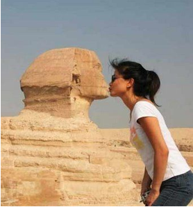
 When I started in this field almost 20 years ago, I thought the problem was: The world is 3D and thus the problem is that there a many to one mapping of the real-world scenes onto a 2D image. I thought the job of a depth camera (such as a ToF Camera) was then to disambiguate the scene using depth, like making sense of the Pictures to the left.
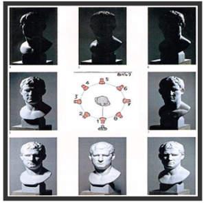
 But I did not realize that scene brightness images here referred to as 2D images are very different from 3D data. A scene can look different under different lighting (see below) and hence there are many 2D images that correspond to a same 3D scene just as there are many 3D scenes that correspond to a 2D image. 3D data is thus fundamentally different from 2D data. It captures the shape of objects not how they may look under some lighting.
I was at lunch with a colleague and was discussing how animals also need good 3D (depth) information about their world to survive. He said the natural world uses stereo (read exclusively). I almost choked in disappointment and when I got home, I did a web search and found that in reality only a few animals used stereo and only in a small number of cases.
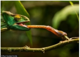
Those animals were mostly predators using stereo to locate their prey in the close-range final strike zone as shown to the left. Most animals (e.g., whales) cannot even have both eyes simultaneously on the target.
 Perhaps the vast majority of animals use motion stereo where the scene is observed from many different positions while the animal is in motion
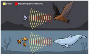
However, echo location which is a form of acoustical ToF is also used in the animal and those creatures rely on it for their existence. A Bat can locate a small insects in darkness meters away. Dolphins can also locate fish the same way.
Microsoft ToF technology is an optical ToF method. The speeds required by the optical transmitting and receiving devices far exceed that possible by biology so there are no biological examples (that I know of). However, I am pretty sure that if it were possible nature could use have used it advantageously 😊. Microsoft ToF can be thought of as a massively parallel optical lidar on a CMOS chip where each pixel in the chip is capable of measuring the arrival time of the light impinging on it.
In Optical ToF light from the laser floods the entire scene simultaneously. The light from the laser then reflects off the various objects in the scene (e.g., face or foot) and is focused by a lens onto pixels in the sensor array. The lens focuses the light from the foot and face onto separate pixels. The pixels receiving light from (e.g.) the face can measure the round trip of light from the laser to the face and back to the sensor.
Each Pixel in the sensor array measures the travel time of light to that Pixel and hence the distance to the object seen by that Pixel. The array of distance values from the Pixel array is called a depth map.
The amplitude of the transmitted light from the laser can be modelled as an offset sine wave (see LHS). The amplitude of the received light at a Pixel is also an offset sine wave but shifted by a phase Φ = 2dω/c proportional to the travelled distance d of the light and the modulation frequency ω of the light amplitude.
Each Pixel is capable of detecting the phase Φ rather than directly the distance d. Therefore, the Microsoft ToF technology is called phased based ToF also known as indirect ToF.
In future posts we will cover more advanced technology topics. Stay tuned…


 Light
Light Dark
Dark
2 comments
Hi Rohan,
We would love to hear your feedback on the post
Very interesting inroduction to ToF, thanks! If you get the distance from the phase, shouldn’t the distance for multiples of the phase be the same? What is done to differentiate these? Or does that mean that ToF only works reliably up to a certain distance?